Chapter 21 Design of implants and factors associated with implant failure (wear, loosening)
Tribology of natural and artificial joints
Kiran Singiseƫ and Paul A. Banaszkiewicz
Introduction#
A classic example is the clinical photograph of an explanted worn PE cup leading on to a discussion of wear.
A good understanding of tribological properft es helps the orthopaedic.
Wear is an A-list topic with similar competency questions in the first part of a viva but unexpected or esoteric higher-order thinking questions in the second part.
Structured oral examination question 1#
Clinical photograph of explanted poly cup with wear and cement
What do you see? Why has this happened?
This is a clinical picture of an explanted PE cup demonstrating acetabular wear (Figure 21.1).
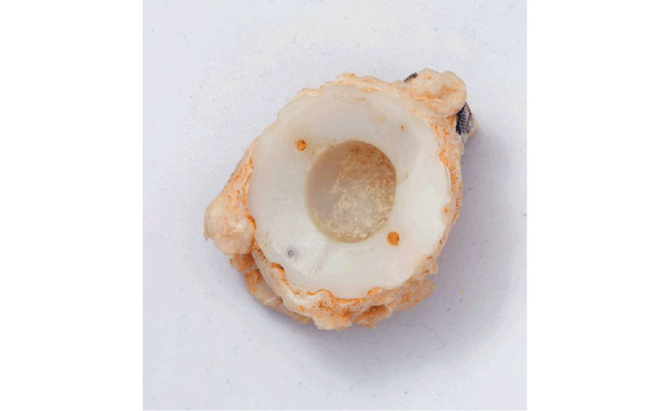
There is quite obvious wear seen on the inside of the acetabular cup, so what do you think has been the most likely cause for revision?
Aseptic loosening.
What do you mean by aseptic loosening?
Aseptic (i.e. not caused by infection) loosening refers to the failure of fixation a t the bone/implant interface.
What is the difference between aseptic loosening and osteolysis.
Aseptic loosening is an umbrella term that is used to describe total joint arthroplasty failure resulting from inadequate initial fixation, mechanical loss of fixation overtime, or biological loss of fixation caused by particle-induced osteolysis around the implant.
What do we mean by wear?
Wear is the removal of material from two surfaces underload, due to a sliding motion between them. Learn one that you are happy with and stick to it.
What are the different types of wear that can occur?
There are two broad categories of wear, (1) mechanical and (2) chemical. Mechanical involves: Abrasive. Adhesive. Fatigue.
Erosive.
Chemical is independent of load and sliding distance:
Corrosion.
What are the various types of mechanical wear?
Asperities on the hard bearing carve ridges (plough/cheese grater effect1) into the softer bearing. An example is between a metal femoral head and a polyethylene liner.
What do you mean by adhesive wear?
Adhesive wear occurs when opposing asperities of two surfaces bond with each other to form a junction .2 This junction is held by intermolecular bonds and generates friction.
What is fatigue w ear?
Cracks propagate, joining together, and the loose material comes away from the surface. An example is delamination of the polyethylene inT KAs.
What is erosive wear?
Erosive wear occurs when hard particles travelling in fluid interposed between two surfaces remove some of the surface as they collide into it.
Corrosive wear?
This is inviting tr ouble.3 Concentrate on the three big wear mechanisms (abrasive, adhesive and fatigue w ear) as these are what the examiners are most familiar with.
Although erosive, the examiners will decide if they want to further probe you for extra details.4.
Third-body wear can be either classified as a subtype of abrasive wear or as a separate, distinct type of wear mechanism.
Erosive wear is classified as either a major or minor cause of mechanical wear depending on which textbook is read.
Can you drawout the different types of wear (Figure 21.2a–21.2c)?

In the exam it is difficult to draw if you are caught cold and need to work it out for the first timeT o be slick, the drawings need to be practised beforehand.
What type of wear has occurred on the PE cup surface?
The majority of the wear pattern would be abrasive. Third-body abrasive wear is also a possibility. This is like having sand in one’s shoes.5 It is a form of abrasive wear that occurs when a hard particle becomes embedded in a soft surface.
How is this wear mechanism in the hip different to that of the knee?
Adhesive and abrasive wear is more pronounced for THA while fatigue w ear (piting and delamination) is more problematic for TKA.
What is the RANKL pathway?
Candidates should be familiar with the RANKL pathway from the Part 1 SBI/EMI paper, but there is a world of difference in answering this topic in a viva exam. The main biological system that leads to osteolysis-induced resorption of bone is the receptor activator of nuclear factor-κB (RANK)/RANK ligand (RANKL) axis Activation of this system results in enhanced osteoclast recruitment and activity adjacent to bone implant surfaces, leading to osteolysis.
Once macrophages are activated by particulate debris, the bone-resorbing cells directly responsible for the pathogenic bone loss in osteolysis.
Other cell types involved in the production of cy tokines and inflammatory mediators include osteoblasts and fibroblasts.
Research suggests that UHMWPE increases the release of RANKL from osteoblasts, while OP Gis significantly inhibited.
Although wear debris may consist of polyethylene, PMMA cement, or metal, by far the great majority of wear particles derives from polyethylene.
What factors affect the degree of osteolysis from wear particles?
Factors affecting osteolysis severity include: 1. Particles within the br oad size range of 0.1–10.0 μm are phagocytosed by macrophages, leading to cellular activation. Those in the size range 0.1–1.0 μm are the most active. 2. Shape of particles (elongated particles are more active compared to round or spherical particles). 3. Volume of particles (the critical volume is 140 mm3/year). 6. Immune response to particles.
What areG ruen zones?
This is a widely used system in which the femoral component interface is considered in seven zones (Figure 21.4).
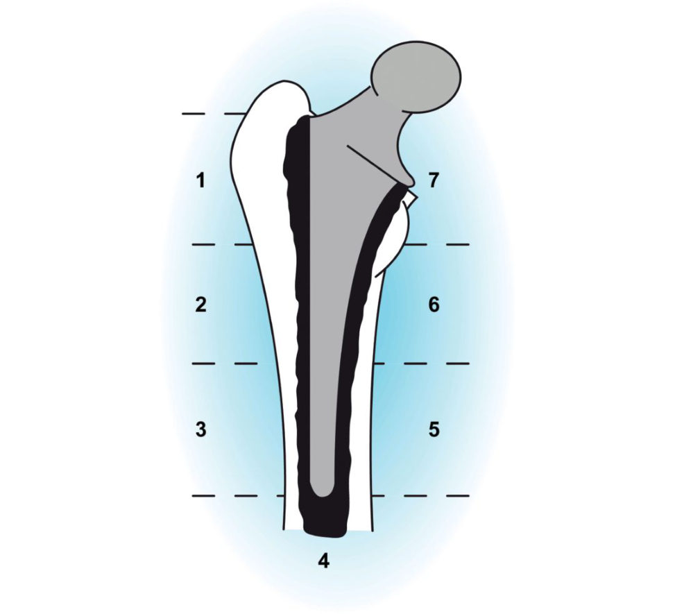
It is the progressive changes seen in serial radiographs that are important in diagnosing osteolysis and femoral stem loosening.
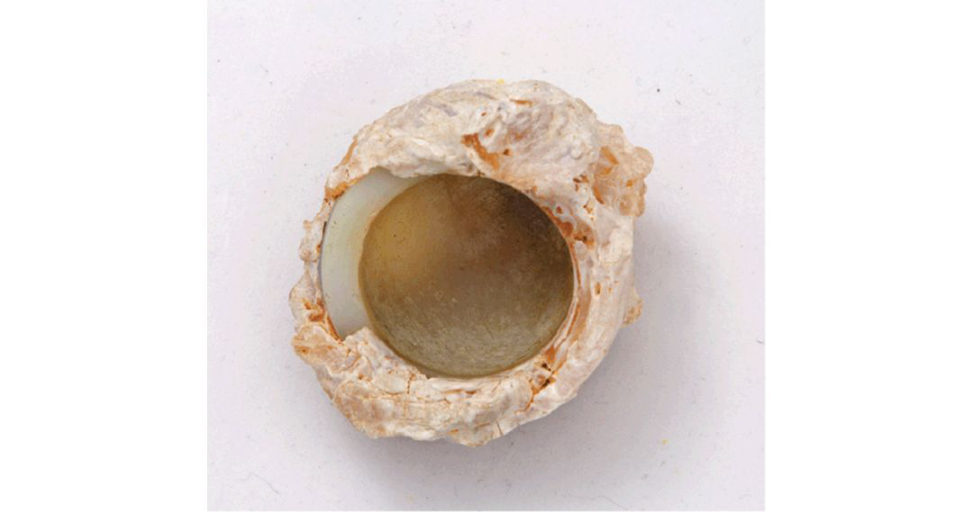
Figure 21.1 Clinical photograph of explanted polyethylene cup demonstrating worn surface.
Figure 21.2a Wear mechanisms. Adhesive wear: opposing asperities bond to each other and shear off as one surface slides over the other.
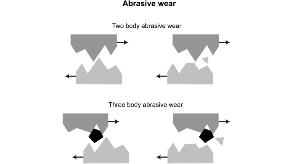
Figure 21.2b Wear mechanisms. Abrasive wear: asperities on the harder material cut into the asperities of the softer material. The new particles become third bodies.
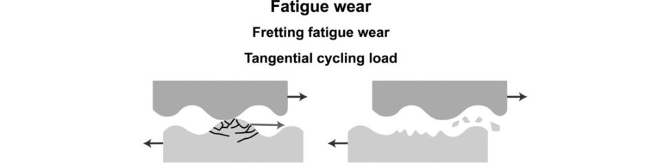
Figure 21.2c Wear mechanisms. Fatigue w ear: cyclical loading causes accumulation of micr o-damage that breaks off as wear particles.
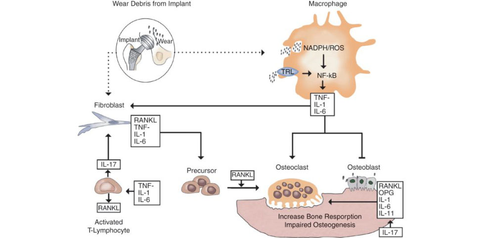
Figure 21.3 Model of interplay between macrophages, fibroblasts, lymphocyte, osteoclasts and osteoblasts in periprosthetic osteolysis. Particles may stimulate macrophages, fibroblasts and osteoblasts directly to induce RANK Land pro-inflammatory cytokines that can induce RANK LItis thought that T cells stimulated by the pro-inflammatory microenvironment may also promote osteoclast formations ynergized with TNF-α, by secreting IL-17. Thus, RANKL , TNF-α, IL-1, IL-6, IL-17 and M-CSF may mediate the differentiation of myeloid precursor cells into multinucleated osteoclasts.6
Experimentally, polymethylmethacrylate (PMMA) and polyethylene (PE) particles have been shown to activate macrophages via the TRL pathway.
Figure 21.4 Gruen zones. Remember 1–7 starting a tGT and ending at calcar.
Structured oral examination question 2#
Wear and osteolysis
A clinical picture of a worn polyethylene cup is shown (Figure 21.5).
Mechanisms of wear.
Osteolysis.
Effective joint space.
What are the mechanisms of wear?
The main mechanisms of wear include abrasive, adhesive and fatigue w ear (see previous answer).
What do we mean by the term ‘osteolysis’?
The core of the biological response that leads to osteolysis involves the receptor activator of NF-κB ligand [RANKL]–RANK axis for osteoclast precursors, resulting in their differentiation and maturation (see previous answer).
What about the importance of macrophages in the pathogenesis of osteolysis?
The cellular response that occurs in osteolysis is dominated by macrophages. Particles ranging from 0.1 to 10 μm in diameter undergo phagocytosis by macrophages. Once activated by particulate debris, macrophages secrete various kinds of mediators to incite a complex cascade of events culminating in osteoclast maturation. Pro-inflammatory mediators such as PGE2, TNF-α and IL-6 are generated in abundance by particle- challenged macrophages.
What do we mean by effective joint space7?
2. All periprosthetic regions that are accessible to joint fluid and its particulate debris. 3. The effective joint space is a concept that describes the entire volumetric area within a hip joint construct that can be infiltrated by PE wear particles and macrophages.
The presence of particulate matter in joint fluid will initiate a localized macrophage-induced phagocytosis and result in bone resorption. If joint fluid is distributed more evenly in an interface, there will be slower resorption of bone accompanied by a fibroblastic response resulting in the radiographic appearance of linear (diffuse) bone loss.
How can you reduce effective joint space?
Reduction in the effective joint space may reduce the amount of osteolysis that can occur. The use of bone screws for fixation of acetabular shells is thought to create new voids in the acetabular bone that increase the effective joint space. Implanting acetabular shells without any screw holes in theory reduces the effective joint space.
What new designs of hip replacements have been introduced to retard osteolysis by limiting the generation and spread of particulate debris?
Improved liner locking mechanisms reduce the amount of motion between shell and PE liner. It has been suggested wear debris can be produced at the interface between the metal acetabular shell and PE liner. Candidates could be moved easily towards discussing improvements in PE manufacture, sterilization, shelf packaging, annealing versus heating , amorphous versus crystalline phase, etc. as part of an evolving viva on wear (advanced questions).
What are the risk factors for osteolysis?
Risk factors can be broken down into patien t-, surgical- and prosthesis-related factors. Implant factors include prosthetic design, bearing couple, PE (manufacturing process, post- manufacturing sterilization, thickness of PE insert (knee) and liner (hip)).
Figure 21.5 Clinical picture demonstrating worn surface of retrieved PE cup.
Structured oral examination question 3#
Wear in THA
Picture of aseptic loosening , what is wear, measures to reduce wear, particle size.
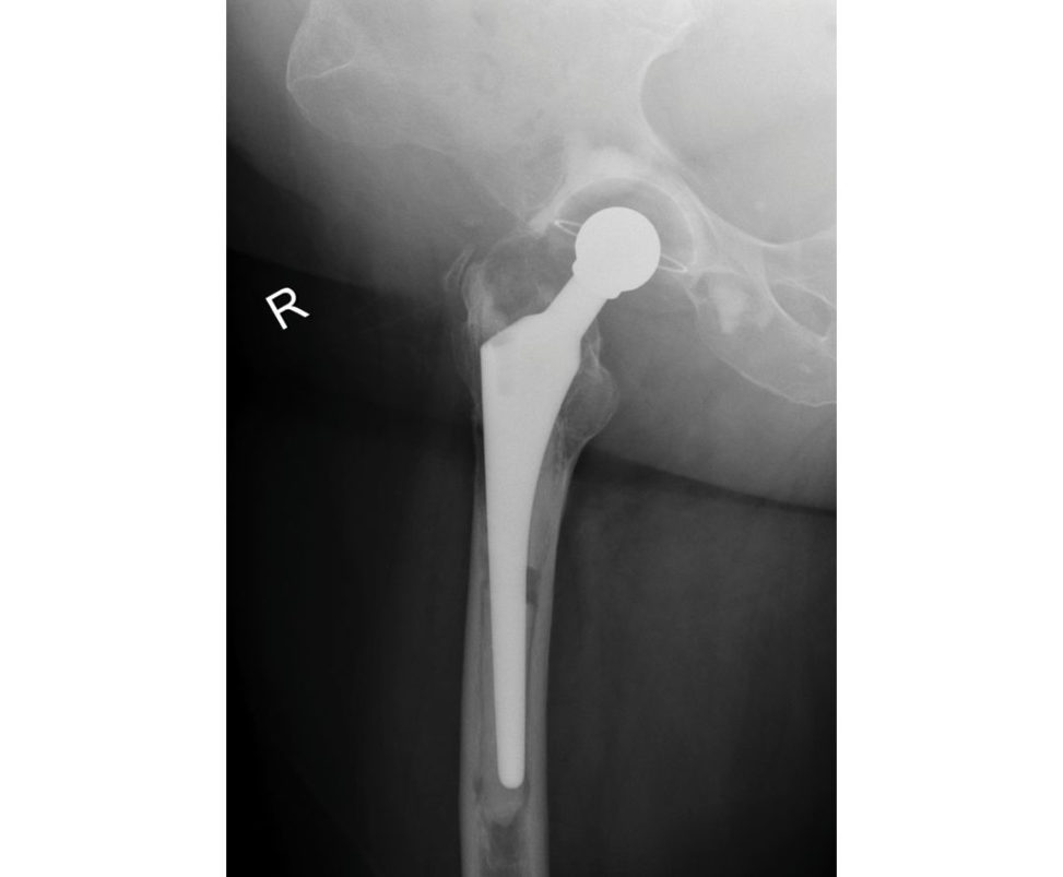
A radiograph of aseptic loosening hip is shown to the candidate (Figure 21.6).
What is wear?
Mechanical wear is the removal of material from two surfaces underload, due to the sliding motion between them.
What are the modes of wear of artificial joints?
The four modes of wear are: Mode 1. Mode 2. Mode 3. Mode 4. McKellop’s classification. Do not confuse with the four Gruen modes of failure of cemented femoral stems or vice versa.9 The fundamental mechanisms of wear include adhesive, abrasive and fatigue w ear.
What measures can betaken to reduce wear?
There is more than enough material to discuss that would use up the full 5 minutes of viva discussion if you are allowed to keep on talking (unlikely, but worth trying). So, a candidate’s leadin phrasing to discuss PE wear could be ‘The main type of wear particle implicated in osteolysis and loosening of total joint replacements is polyethylene. Methods to improve the wear characteristics of PE include ’: Manufacturing techniques.
Another possible option ist o discuss:
Surgeon (technique) factors:
Implant selection, a voidance of implant malalignment, accurate restoration of mechanical axis joint.
Patient factors:
Weight (weight reduction).
Activity le vel (avoidance of excessive activities, eg. waterskiing, treadmill running, etc.).
Implant design.10 Decide on whether to discuss hips or knees or both.
Hips.
Offset. Decreasing offset increases joint reaction forces.
Choice of bearing couple (MoP, CoP, MoM).
Head size.
Knees.
Conformity.
Thickness of PE (minimum 8 mm).
Femoral rollback.
Figure 21.6 Anteroposterior (AP) radiograph, pelvis, demonstrating loose right THA. Cement fracture and femoral stem and cup migration. Gruen mode 1a failure.
Structured oral examination question 4#
Wear in TKA
Polyethylene wear in TKA: discuss all factors.11
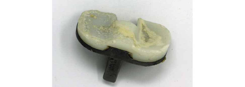
What does the picture show (Figure 21.7)? CANDIDATE 1: A worn tibial tray. CANDIDATE 2: A worn PE tibial insert. It looks like it is a CR-retaining ploy. There is evidence of severe delamination with uneven wear more pronounced medially. Discoloration is as a dark yellow tint representative of polyethylene oxidation. Discuss the factors associated with PE wear in TKA.
Ultra-high molecular polyethylene wear debris triggering osteolysis is one of the major causes of failure of TKA. Varus alignment of implants leads to accelerated medial PE wear and the risk of early failure. Varus placement of the tibial component > 3° leads to almost double the PE volumetric penetration rate. This is compounded by the roughness of the metal tibial tray, resulting in increased PE particle generation leading to osteolysis. This can be particularly severe in tibial tr ays with holes for fixation screws around which osteolytic lesions can develop. Additional component features that increase wear include thinner polyethylene inserts, some non- cemented tibial baseplates supplemented with tibial screws, and metal-backed patellar components. The change from sterilization of PE by gamma radiation in airt o an inert gas has resulted in much lower rates of osteolysis at 10 years post surgery.
The mechanism of wear between these two joints is different.THA wear is mostly due to micro-adhesion.
Most supporting evidence for HXPLE in knee arthroplasty is derived from in-vitro wear simulator studies that show a reduction of w ear of up to 60%.
conventional UHMWPE bearings have all found no significant difference in clinical or radiological outcomes between the two bearings.12,13,14.
HXLPE had a lower cumulative percentage revision than conventional polyethylene at 5 years (4.0% vs 2.6%) and
10 years (5.8% vs 3.6%).
It is recognized that failed TKA have larger flake-shaped debris, which elicits a tissue response characterized by fewer macrophages.
A clinical picture of a tibial insert demonstrating a white subsurface oxidized band of PE is another classic lead-in prop to discuss PE wear in TKA.
What are the wear mechanisms in TKA?
Three main wear mechanisms can beseen in TKA.15 These are adhesive, abrasive and surface fatigue. Adhesive wear: the bonds formed between different materials are stronger than the specific material properties of either surface and therefore pullout fragments from one surface to another. Abrasive wear: a harder rougher material ploughs through a softer material.
Figure 21.7 Worn PE tibial tray. Delamination is seen as thin sheets of polyethylene separated from the surface.
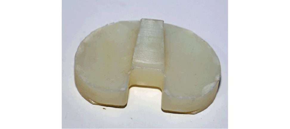
Figure 21.8 Retrieval PE insert demonstrating classic white band defect of oxidation located 1–2 mm below the machined surface of PE.
What wear damage occurs at the tibial PE surfaces of aTKA?
Hood et al.16 described seven types of wear mechanism damage at the articulating surfaces of TKA: Burnishing (polishing).
Burnishing: contact areas are polished due to a combination of abrasive and adhesive wear.
Scratching: this is caused by abrasive wear.
Abrasion: characterized as a shredding of the polyethylene surface and classified as a mode of abrasive wear.
Pit inga mode of fatigue w ear that is characterized by the formation of millime tre-sized craters
(Figure 21.9). It is considered to be a more benign wear mechanism that does not provoke an osteolytic response.
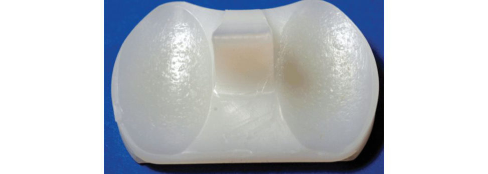
Third-body wear: wear debris can act as third-body particles, initiating w ear by rubbing at the bearing surfaces.
Delamination ( Figure 21.10), and can result in catastrophic wear.
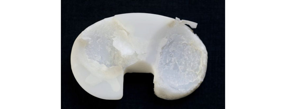
There is gross disruption of the material to a depth of 0.5 mm or more due to the formation and propagation of subsurface cracks.
Figure 21.9 Piting small cr ater-like surface defects.
Figure 21.10 Delamination of PE.
More severe plastic deformation of the tibial insert may be an indication of malalignment or a mismatch of component sizes.
PE wear in knee arthroplasty occurs from a combination of rolling, rotation motions between the bearing surfaces.
Strategies to reduce polyethylene wear include the following.
Improving implant design.
Congruent bearing designs lower the amount of cross-shear stresses.
The sagift al plane should be concave or dished and the individual medial and lateral tibial plateaus should also be dished in the coronal plane.
Improved locking mechanisms of modular tibial components to reduce potential back side wear.
Highly polished tibial baseplate.
A rotating yet flat PE bearing is matched against a highly polished cobalt chromium surface.
Monobloc tibial components. The PE bearing surface is direct compression-moulded to the tibial baseplate.
All polyethylene tibial components have been used in an attempt to decrease or eliminate the problems associated with backside wear.
Improvements in the quality of ultrahigh-molecular-weight PE.
Improved sterilization techniques (gamma irradiation inert atmosphere).
Development of newer, highly cross-linked PE with the introduction of vitaminE and sequential annealing.
Refining surgical techniques.
Computer navigation.
Fellowship-trained surgeons.
Is there any evidence that all-polyethylene tibial components reduce wear (Figure 21.11)?
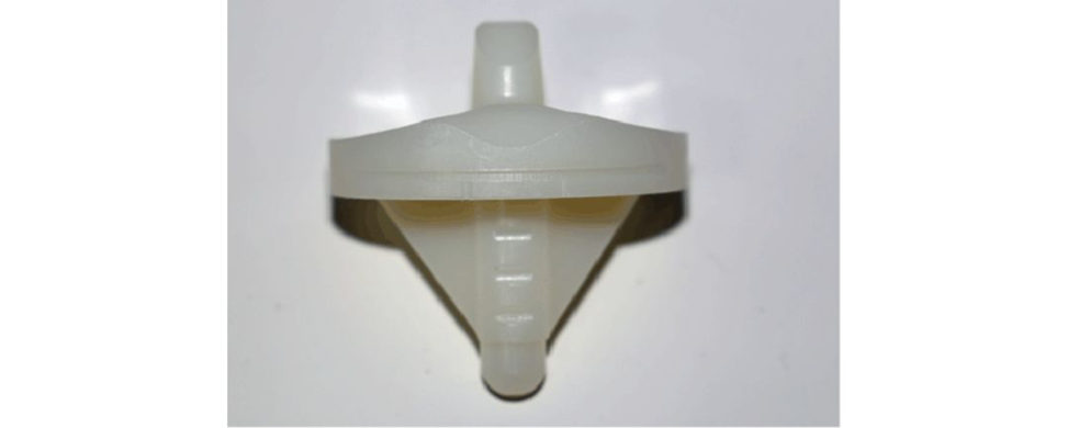
With all-polyethylene tibial (AP T; Figure 21.11) the same amount of tibial resection allows for a thicker PE to be used, potentially increasing the lifetime of the prosthesis if wear rates are equivalent, as less tibial resection will be required to achieve the same poly thickness as a design with a metal tray, resulting in a larger metaphyseal surface area and the ability to use larger tibial component sizes, reducing the magnitude of contact stresses transmift ed across the joint while also preserving metaphyseal bone stock.17
What do we mean by conformity?
Contact stresses experienced at the PE surface are inversely proportional to the degree of conformity between the femoral condyle and the tibial PE insert.
So why don’t we just go with highly conforming knee designs?
Highly conforming TKA designs significantly increase the stresses transmift ed to the fixation interface and increase the risk of early aseptic loosening.
What about mobile bearings?
In-vitro wear studies have shown that mobile bearing produces less wear compared to fixed designs.
What about surgeon factors?
Surgeon-controlled strategies recommended for reduction of PE w ear include meticulous attention to ligament balancing.
What else?
Ideally, a fellowship-trained arthroplasty surgeon.
What else?
GIRFT (geting it right first time). Computer navigation.
Is there any evidence that computer navigation improves the accuracy of implant positioning?
There is some evidence that computer navigation reduces the number ofT KAs that have a coronal malalignment of more than 3°.
Which paper?
I am not familiar with the specific papers, but the general literature suggests better alignment with navigation.
Figure 21.11 All-polyethylene tibial component (APT), posterior stabilized design.
Reference#
Bauwens K, Matihes G, Wich M, et al. Navigated total knee replacement. A meta-analysis. J Bone Joint
Surg [Am]. 2007;89A:261–269.
Although coronal malalignment is reduced, mean alignment and mechanical axis did not differ between navigated and conventional TKRA groups.
Is there any evidence that computer navigation improves the survival of a knee prosthesis?
It is very difficult to prove that computer navigation definitely reduces the need for revision surgery. Recent Australian Registry data suggest there may be a small advantage, particularly in younger patients, as there is a small reduction in the rate of revision for loosening in this group.
What about the use of alternative bearings?
Some surgeons have begun using oxidized zirconium femoral components as a means of reducing polyethylene wear. This technology incorporates a zirconium oxide ceramic coating on a zirconium metal alloy femoral component.
Any long-term results reported?
Ten-year results were reported by Pinczewski et al. from Australia.18 They showed comparable rates of survival with other implants and excellent functional outcomes 10 years postoperatively.
Any concerns with the paper?
Single-surgeon series in a tertiary specialized referral centre that may not reflect the average standard knee arthroplasty surgeon practice.
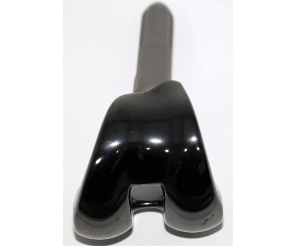
Figure 21.12 Oxium-coated femoral knee implant. During manufacture, OXINIUM implants undergo a process that transforms the implant’s surface into a hard, ceramicized metal.
Structured oral examination question 5#
The candidate is shown a clinical picture of catastrophic PE failure in TKA (Figure 21.13).
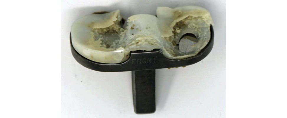
Remember to structure your answer (1) PE thickness, (2) articular surface design, (3) knee kinematics, (4) PE manufacture, (5) PE sterilization and (6) surgical technique. This is a clinical photograph of an explanted tibial knee replacement component demonstrating catastrophic PE failure.
Figure 21.13 Catastrophic failure of PE tibial insert.
Structured oral examination question 6#
Charnley THA
Polyethylene cup: what is polyethylene, manufacturing advances, wear, what is the stem made from, stress–strain of the stem
What is polyethylene?
UHMWPE is a member of the polyethylene family of polymers with the repeat unit [C2H4]n, with n denoting the degree of polymerization. It is a linear (non-branching), semi-crystalline polymer which can be described as a two-phase composite of crystalline and amorphous phases.
How is PE manufactured?
Polyethylene resin is simultaneously heated and pressurized within an evacuated chamber. As the solid polyethylene forms, it is extruded through an open extrusion port within the chamber. A primitive method of polyethylene manufacture, but cheap. Because the extrusion process is non-continuous, inconsistencies can be found within the solid polyethylene bar stock. Calcium stearate crystals could be found between the particles of polyethylene, resulting infusion defects that became the point of crack initiation and propagation.
The resin is directly moulded into the finished implant.
There is no secondary machining of the bearing surface. Best wear profile.
Direct compression moulding has a lower susceptibility to fatigue cr ack formation and propagation.
Hot isostatic pressing (HIPing) into bars.
Multistep conversion process of resin powder into stock material.
What do we mean by the cuting tool effect of polyethylene?
In a machined polyethylene insert, machine marks from the lathe create numerous micron- size grooves and shreds on the bearing surface. As the high-speed cuting la the removes PE, the remaining nearby PE is stretched. Stretching occurs in the amorphous areas of PE and is most pronounced in the PE 1–2 mm below the surface of the cut PE.
What manufacturing advances have occurred with PE?
The advent of highly cross-linked PE (HXLPE) has been shown to improve wear rates in hip arthroplasty. Compared to standard PE, HXLPE has: Better wear resistance. To score a 7 a candidate may need to discuss supportive literature of improved implant survivorship with HXLPE in THA. To score an 8, a candidate may need to discuss the controversies of HXLPE use in TKA.
What do we mean by cross-linking?
By removing atoms or side groups from adjacent chains, covalent bonds can form that link chains together, inhibit relative molecular movement and as such modify the physical properties of the materials.
What methods are used for PE sterilization?
Sterilization methods can be divided into (1) non-energetic (nor adiation) and (2) energetic (using radiation methods. Both ethylene oxide and gas plasma sterilization a void free radical production but do not allow cross-linking of PE. As such, they have a higher wear rate compared to cross-linked PE. Gamma sterilization in air: this makes PE susceptible to oxygenation. Irradiation in the presence of oxygen leads to chain scission of the polyethylene long chain and free radical generation a t the crystal surfaces. Cross-linked PE has improved resistance to adhesive and abrasive wear. This results in an increase in wear resistance. Two different approaches are adopted to achieve oxidation resistance. 1. Annealing: this involves a single thermal treatment below the melting temperature of UHMWPE so that crystallinity and mechanical properties are preserved. 2. Remelting: pos t-irradiation remelting of the polymer above the crystalline transition.
What is the Charnley femoral stem made of?
The original stem was a monoblock, flat-backed design with a polished surface manufactured out of EN58J stainless steel (Figure 21.14).
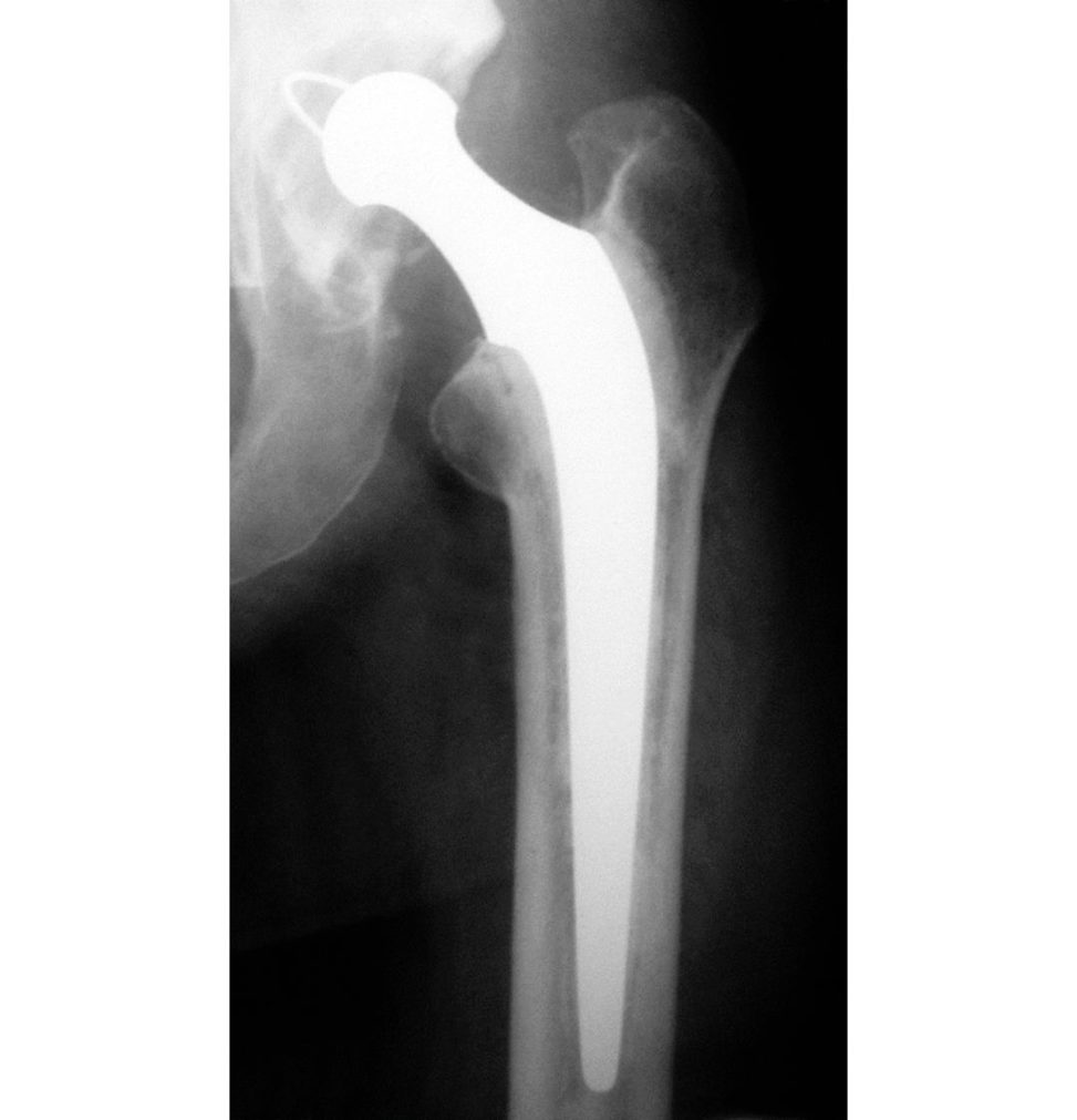
Figure 21.14 Radiograph of Charnley total hip arthroplasty.
Score 7
Rates of stem fractures led to change in stem surface in 1969 to am aft finish using the vaquasheen process, which deliberately surface-hardened the metal to resist fracture.
In 1975, anteroposterior Cobra flanges were added to the stem to prevent the escape of cement at the level of the neck resection and also pressurize the cementin the femoral canal.
These changes resulted in a shift in the behaviour of the stem to a composite beam where its predecessor had obeyed the taper-slip principle.
In 1982, the material was again changed to Ortron 90, a cold-worked stainless steel with high fatigue strength.
Gold medal
When Charnley changed his stem from the flatback to the Cobra design, the biomechanical characteristics were changed from a tapered polished (force-closed) to a shape-closed or composite beam biomechanical design. If you are feeling very confident you can discuss the change in stem behaviour with change in Charnley stem.
What about the stress–strain curve of the stem?
The slope of the stress–strain curve of the stem would be the elastic modulus of stainless steel.
What are the risk factors for femoral stem fracture (Figure 21.15)?
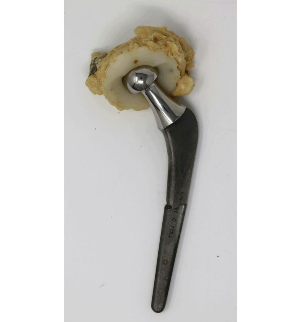
Multiple risk factors for prosthetics tem fracture include: High BMI. Varus stem positioning.
What is the incidence of Charnley stem fracture?
The first generation of Charnle y stainless steel femoral stems fractured in approximately 4.1% of patients.
Improvements in stem design and metallurgy have markedly reduced the incidence of femoral stem fracture.
This is the basic science viva, so candidates are less likely to be asked how they would revise a broken femoral Charnley stem.
Figure 21.15 Explanted picture of broken Charnley femoral stem.
Structured oral examination question 7#
TK Aloose implant
Same discussion of wear, mechanics of loosening and biology of osteolysis as in previous questions.
Discussion about cement – what is it, materials, properties, etc.
Wedges for reconstruction of tibial defect, how wedges work, why wedges and not cement for buildup etc.
What types of tibial bone loss can occur with primary THA?
Large posteromedial asymmetrical osseous defects are often seen in the proximal tibia while performing a primary total knee arthroplasty (TK Ain severe varus knees. Depending upon the size of the defect, these can be treated with cementoplasty, structural bone gratis or metallic wedges.
What about cement?
Cement is cost-effectiv e, but it cannot be used to address large bony defects. Thermal necrosis of bone can occur as well as shrinkage when used in large quanties.
How do augments work for build-up of bone defects?
Metal augments allow rapid filling of bone defects that have been geometrically shaped with instruments. Using thick augments (30 mm) may result in a painful subcutaneous bulge in the tibia or in the distal femur. Therefore, to achieve stable fixation a pr ess-fit metaphyseal femoral sleeve can be used to enhance the rotational stability of the femoral component.
Anything else that can be used to deal with bone loss?
Extensive bone loss can beseen with revision TKA. A broach technique is used to prepare the bone for the press-fit implant.
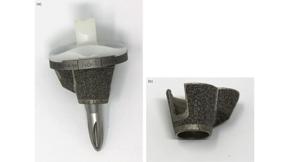
Metaphyseal filling titanium cones (Figure 21.17a and 21.17b).
I would use impacted morsellized bone graft when the reis a contained bone loss larger than 10 mm. I would avoid its use if there was significant cortical bone loss or uncontained defects.
Megaprostheses: high complication rate but the surgical procedure and rehabilitation are rapid.
High rate of infection (~5%) that can often be followed by amputation.
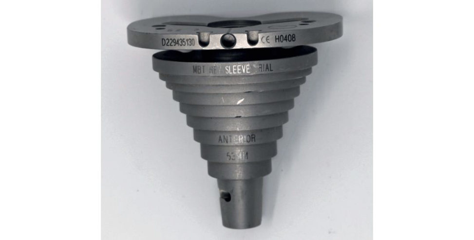
Figure 21.16 Metaphyseal sleeve. The broad tibial sleeve contacts the remaining proximal tibial cortex impacting stability.
Figure 21.17a and 21.17b Metaphyseal filling titanium cones used to reconstruct metaphyseal bone loss in the tibia or femur.
Structured oral examination question 8#
Cementing technique THA
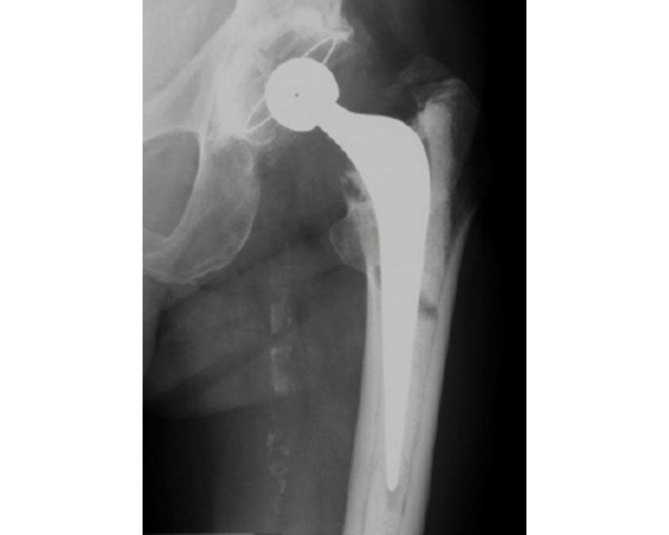
Picture of broken cement mantle (Figure 21.18) – reasons for this.
What are the reasons for a broken cement mantle?
The early development of stem–cement interface debonding (separation) and subsequent cement fracture are thought to be the initiating events of aseptic loosening. It is important to reduce cement stresses so as to minimize the risk of cement debonding and fracture.
So how can high cement stresses be avoided?
By the creation of an optimally thick symmetric and homogeneous cement mantle.
So how do we achieve this?
Stresses experienced in the cement mantle have been shown to be highest at the stem tip and secondarily at the proximal–medial cement mantle. Stem malalignment produces non-uniform cement mantle thickness in key areas.
Can you be more specific19?
A proximal–medial cement mantle greater than 10 mm orless than 2 mm in thickness is associated with a significant increase in cement fracture, radiolucent lines at the prosthesis–cement interface and progressive component loosening when compared to proximal–medial cement mantles that measure 2–5 mm in thickness.20
An asymmetrical distal cement mantle significantly increases the risk of implant failure.
Inadequate centralization of the s tem or malrotation will result in excessively thinned areas of distal cement, increased cement strains, prosthesis bone contact.
Preserving < 2 mm of proximal–medial cancellous bone for 30 mm distal to the femoral neck cut increases cement mantle thickness, the incidence of cement fractures.
Best results for femoral components allow for 2–5 mm proximal–medial thickness of cement mantle, less than 2 mm of proximal–medial cancellous bone thickness, a stem that fills more than half the distal part of the medullary canal and a stem in neutral orientation. Worst results for femoral components occur with a cement mantle thickness > 10 mm, a femur with more than 2 mm proximal–medial cancellous bone, a stem that fills half orless of the medullary canal and those in varus orientation.
What would you inform your juniors about too litile or too much cement?
The femoral stems of hips that have a 2–5 mm thick cement mantle in the proximal medial region have a better outcome than stems implanted.
What about the cement, how can this be improved?
improved interface adherence) to increase strain resistance, microfractures should lead to improved long-term results from cement fixation.
What measures can betaken intra operatively to improve the quality of the cement mantle?
Figure 21.18 Anteroposterior radiograph showing the Exeter total hip replacement with radiolucent lines around the femoral component and fracture of the cement mantle.
1. Canal preparation
Use of correctly sized broaches that allow a mantle of adequate thickness.
hypotensive analgesia to reduce bleeding, avoidance of blood/cement occlusions.
2. Cement preparation
Occlusion of the canal using a distal plug, retrograde filling of the canal and cement gun pressurization of the cement column with a tight proximal seal are essential in achieving an interdigitating , uniform and homogeneous cement mantle.
How can the cement mantle be optimized How can we obtain a high-quality cement mantle?
Methods forcement fixation optimization include: Cement gun pressurization (enhances interdigitation) of the cement column with a tight proximal seal (femoral pressurizer). Porosity reduction (v acuum-mixing) which leads to reduced stress points in cement. Cement mantle thickness > 2 mm. Stem centralizer (reduces risk of stem malpositioning to decrease stress on the cement mantle).
Have you heard of boneloc bone cement?
This is a bone cement that was withdrawn quite soon after introduction because of unacceptable revision rates with its use.
What is the ideal cement mantle thickness?
I would aim for a cement mantle thickness greater than 2 mm as any less than this increases the risk of cement mantle fracture.
Have you heard of the French paradox?
No, I am sorry I haven’t. Int heUK and USA, the first technique aims to produce a complete cement mantle of at least 2 mm in thickness and without ‘windows’. This has been called the French paradox in which implantation of a canal-filling femoral component in a line-to-line manner is associated with a thin cement mantle.21
a canal-filling stem was supported mainly by cortical bone, subjected to low stresses.
Barracks grading of cement.22,23 Generations of cementing technique. Categories of loosening of cemented stems (Harris). Exeter vs Charnley stem design.
Structured oral examination question 9#
Wear in TKA
What types of wear occur in TKA?
There are two main types of tibial component wear in TKA, (1) adhesive and abrasive wear and (2) fatigue damage (piting and delamination ).
Fatigue w ear in tibial poly – what, why, where?
The appearance of fatigue w ear damage is primarily associated with cyclic compressive- tensile loading at the bearing surface, which generates subsurface tensile stresses that initiate and propagate cracks to form delamination and piting damage. Instances of fatigue w ear and fracture have repeatedly occurred over the history of UHMWPE use in TJR due to changes in molecular weight, fusion defects, crystallinity or cross-linking that can reduce the polymer’s resistance to crack initiation and growth. Fusion defects can exist along particle boundaries, acting as cr ack nucleation sites for fatigue w ear (delamination orpit ing) under cyclic sliding contact. This renders tibial PE inserts more susceptible to fatigue fracture or delamination w ear in the presence of high cyclic contact stresses or at sites of stress concentration, especially in a non-c onforming bearing surface.
With melting of HCL PEther e is lowered crystallinity with improved wear characteristics but reduced mechanical properties.
Annealing avoids the reduction in the crystalline structure, but there is incomplete elimination of free radicals.
The JBJS review article ‘Osteolysis complicating total knee arthroplasty’24 provides a good framework for this viva topic.
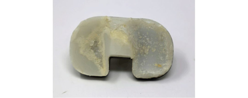
Figure 21.19 Tibial PE insert demonstrating fatigue failure. Fatigue failure is the formation of subsurface cracks in the polyethylene caused by cycles of loading and unloading of the joint, which then propagate and create particles that are shed into the joint space.
Structured oral examination question 10#
Osteolysis
The candidate is shown a picture of a THA with femoral osteolysis (Figure 21.20).
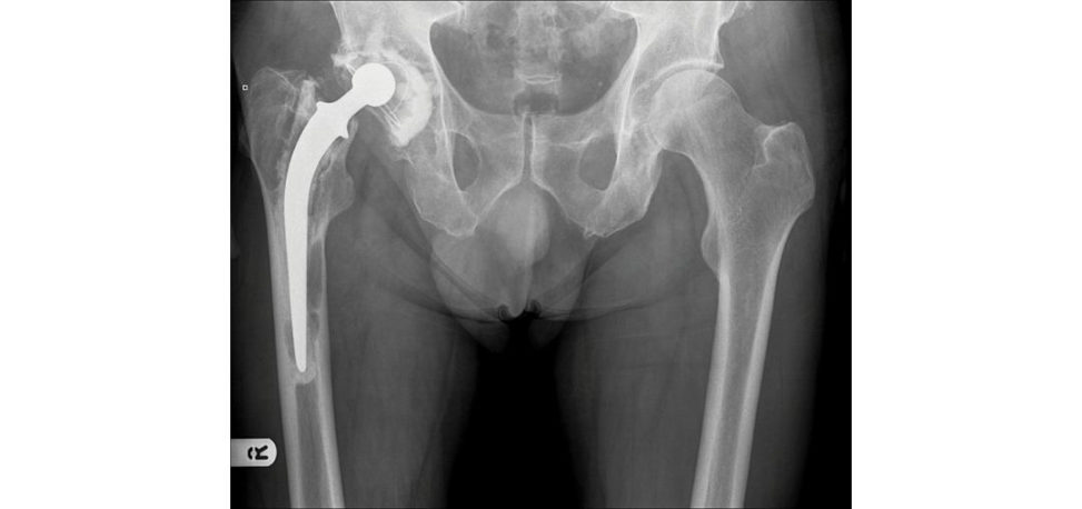
This is essentially a question on osteolysis and wear. Wear debris from prosthetic materials or bone cement is phagocytosed by macrophages causing release of various mediators.
What size of PE material?
Studies have demonstrated that wear particles phagocytosed by macrophages elicited different responses depending on particle size Particles measuring < 5 μm in size generated a strong mononuclear macrophage response, whereas larger particles resulted in more multinucleated giant cells. The debris generated from prosthetic w ear triggers a cascade of macrophage cytokines, such as interleukin-1-beta (IL-1β) and tumour necrosis factor-alpha (TNF-α), among others, resulting in osteoclastic bone resorption and eventually leading to osteolysis. Material properties (HXLPE vs UHMWPE): higher percentages of small wear particles (0.1 –1 μm range) are produced during laboratory wear of HXLPE than conventional PE. The cellular mechanism of particle-induced osteolysis is that macrophages in the periprosthetic tissues phagocytose wear particles and become activated releasing an array of cytokines, leading to increased osteoclastic resorption of the adjacent bone and the production of the granulomatous tissue that fills the resorbed space.
The majority of bone resorption occurs from osteoclasts recruited to sites of osteolysis and activated by the osteoclastogenic molecules.
The major pathway of osteoclastogenesis is the production of RANKL by osteoblastic stromal cells and binding of RANKL to its cognate receptor, RANK, on the surface of osteoclast precursors, stimulating these cells to differentiate into mature, active osteoclasts capable of resorbing bone.
Other cell types, including fibroblasts, osteocytes and activated T cells, also produce RANK Land are capable of stimulating osteoclast ogenesis.
Exposure of osteoblast-like cells toPE has been shown to induce changes in the rate of cell proliferation, to decrease alkaline phosphatase activity , and to increase the production ofos teoclastogenic mediators, such as PGE2, IL-6, GM-CSF, RANK Land nitric oxide.
Types of wear and modes of wear?
See previous viva questions.
Figure 21.20 Anteroposterior (AP) radiograph, pelvis, demonstrating femoral osteolysis.
Structured oral examination question 11#
Implant materials
Total knee arthroplasty components and the materials used. Discussions about the advantages of cobalt chrome versus stainless steel and then polyethylene manufacture and sterilization. The implant biomaterials used in total knee arthroplasty include: Stainless steel. Its use in TK Awas restricted because other metallic alloys such as Ti-based and Co–Cr-based alloys exhibited superior mechanical (yield strength) and corrosion properties. Newer implant stainless steel contains a high chromium, molybdenum and nitrogen content, making it stronger and resistant to local corrosion. There are several methods that can be used to modify Young’s elastic modulus of stainless steel.
What does the 316L stand for in stainless steel?
The 3 stands for molybdenum (3%), 16 for nickel (16%) and L for low carbon (any stainless steel with less than 0.03% carbon).
Cobalt chromium
Used as a bearing surface as it is very smooth and scratch resistant. It has a high Young’s modulus of elasticity and therefore risk of stress shielding.
Titanium
Young’s modulus of elasticity is closer to bone; therefore, it is more ductile, with good corrosion resistance, ability to integrate with bone, inert, biocompatible and extremely strong.
Expensive.
Can you give me an example of a titanium alloy used?
Titanium alloy 6AL4V (titanium 89%, aluminium 6%, vanadium 4%, others 1%). Oxidized zirconium (OxZr): developed as an alternative bearing material for TJA. Higher-order thinking (HOT): puting this all together, cobalt–chromium alloys remain the predominant material (gold standard) used for TKA. There is a worry of increased PE tibial back side wear if titanium is used in place of cobalt–chromium. All poly tibia inserts were introduced to reduce wear and cost, but had poorer clinical results than conventional me tal tibia baseplates.
Structured oral examination question 12#
Wear and osteolysis
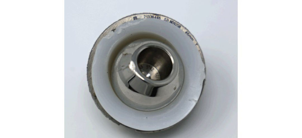
Acetabular cup. Explanted and worn.
What side is up? Divots on the other side may be from neck impingement.
How can you prevent wear? Implant factors/surgical factors.
Implant material, poly manufacturing process and direct compression moulding.
What about the head – we could use ceramics as less rough and better scratch profile.
Tell me about problems with wear – go through the whole RANK/RANKL discussion.
What side is up?
There is eccentric PE wear in the cup superiorly (Figure 21.21).
What is the difference between PE creep and wear (Figure 21.22)?
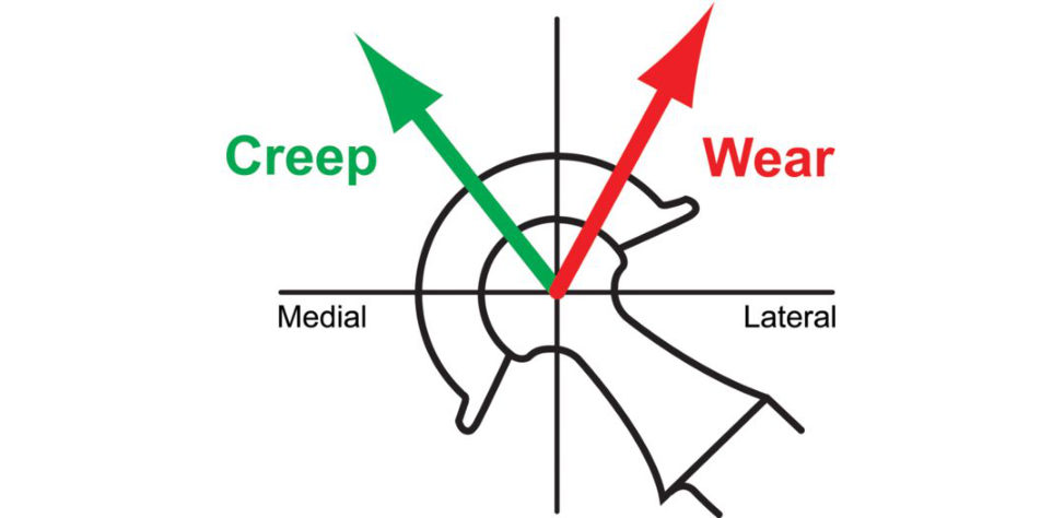
Creep is normal loading of the polyethylene cup and is superomedial.
This worn bit here.
I pointed out divots on the outer side of the PE cup and said this could be due to neck impingement.
How do you prevent impingement?
Impingement in THA is both implant- and surgeon-dependent. The implant design factors are those that influence the femoral head–neck ratio aswell as features of acetabular design.
What factors affect the head–neck ratio?
Cam-type impingement can occur with use of a small head on a large circular taper or the use of a skirted femoral head.
What features increase acetabular impingement?
Features that increase acetabular impingement include the chamfer geometry of the rim of the polyethylene and the presence of an extended-rim (hooded) liner, particularly if the hood is incorrectly positioned in the hip.
What do you mean by chamfer geometry?
The chamfer geometry is where the liner rim is sloped.
How do you reduce the chances of impingement occurring?
Correct restoration of femoral offset and leg length.
How do you ensure correct leg length and restoration of femoral offset?
It is essential to template the hip preoperatively and use a calliper-type pin device intra operatively to check leg length.
How can you prevent wear?
This is best discussed in terms of patien t-related factors, implant-related factors and surgical factors (see above). Implant material – the poly manufacturing process that has the best wear profile is direct compression moulding into the shape of the desired product. Conventional PE used in hip arthroplasty was sterilized by gamma radiation in air , which offered the benefit of cross-linking but at the same time, this process produced free radicals that oxidized in air, leading to increased wear. High-dose gamma irradiation of polyethylene is not a sterilization process but a procedure to produce highly cross-linked PE.
Tell me about shelf oxidation.
Oxidative embritilemen t (characteristically identified as a subsurface white bandis atiribut ed to gamma sterilization in air.
How does femoral head size affect wear?
With conventional UHMWPE the larger the femoral head the greater the volumetric wear. The smaller the head size the greater the amount of linear wear. Volumetric wear is proportional to the frictional torque of the THA. Therefore, an increase in femoral head size increases frictional torque and related volumetric wear.
Figure 21.21 PE cup demonstrating superior eccentric wear.
Figure 21.22 Difference between PE cup creep and wear.
This is the basis of Charnley’s LFA.
How can wear of a THA be measured?
1. Linear wear: the thickness of the acetabular cup decreases as it wears with use. Volumetric wear is related to linear wear by the equation Volumetric wear [mm3] = π × (radius of femoral head [mm])2 × linear wear [mm] As such, a larger diameter femoral head produces more volumetric wear for the same linear wear.
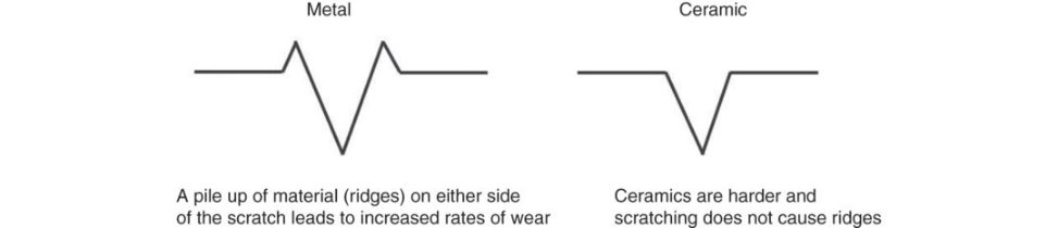
Can you tell me about the scratch profile of ceramic compared to metal (Figure 21.23)?

Best to draw this out if allowed (Figure 21.24). Scratches of the femoral head can lead to an increased rate of PE wear. Additionally , ceramic has a more rounded surface profile with fewer sharp ridges than a metal surface, thus making it better suited for a bearing surface.
Ceramic is chemically inert. In the aqueous environment of the body, passive oxide films form on the surface of metal femoral heads. These consequences are avoided with ceramic heads.
Figure 21.23 Scratch profile of metal and ceramic heads.
Figure 21.24 Candidate drawing of scratch profile.
What factors affect wear of a hard-on-soft bearing surface?
For the head (hard-bearing surface): Surface roughness. These areas increase PE wear. Hardness (scratch resistance, adhesive wear). Its modification by irradiation.
References
1. Buzzword.
2. Buzzword again.
3. This applies in general to most of your answers. Unnecessary.
Although the examiners are more interested in the different types of mechanical wear, we would still mention it.
5. Analogies are helpful for the purpose of explanation or clarification.
6. Lee S-S, Purdue PE, Nam J-S. Inflammatory periprosthetic bone loss. In Inflammatory Diseases – Immunopathology, Clinical and Pharmacological Bases. IntechOpen; 2012. DOI: 10.5772/25558.
7. Banaszkiewicz PA. 2014, Springer. p. 85–87
8. Schmalzried T, Jasty M, and Harris WH. JBJS. 1992;74(6):849–863.
9. Quite common in practice viva sin underprepared candidates a few weeks away from siting the actual part 2 exam.
10. This may be the main thrust of the topic.
11. This is a gift.
12. Kim Y-H, Park JW, Kim JS, Lee JH. 2015;473(11):3588–3594.
13. Kindsfater KA, Pomeroy D, Clark CR, Gruen TA, Murphy J, Him denS. J Arthropl. 2015;30(8):1333–1338.
14. Lachiewicz PF, Soileau ES. A randomized trial. Clin Orthop Rel Res. 2016;474(1):88–95.
15. Rules need to be broken if needs be.
16. Hood RW, Wright TM, Burstein AH. J Biomed MatRes Part A. 1983;17(5):829–842.
17. Doran J, YuS Smith D, Iorio R. 2015;28(05):382–389.
18. AhmedI, Salmon LJ, Waller A, Watanabe H, Roe JP, Pinczewski LA. 2016;98(1):58–64.
19. Dennis DA, Lynch CB. Optimizing the femoral component cement mantle in total hip arthroplasty. Orthopedics. 2005;28(8):S867–871.
20. Ebramzadeh E, Sarmiento A, McKellop HA, et al. J Bone Joint Surg Am. 1994;76:77–87.
21. El Masri F, Kerboull M, Kerboull L, Courpied JP, Hamadouche M.
22. Barrack RL, Mulroy R, Harris WH. A 12-year radiographic review. 1992;74(3):385–389.
23. Banaszkiewicz PA. In Classic Papers in Orthopaedics. 2014, Springer. p. 31–34.
24. Gilbert TJ, Anoushiravani AA, Sayeed Z, Chambers MC, El-Othmani MM, Saleh KJ. JBJS Rev.